
Young’s Double-Slit Experiment - Book Excerpt #2
The Provisional Triumph of the Wave Theory

This is section I.3 (that builds upon the previous sections here) of the first volume of my book, “Quantum Physics: An Overview of a Weird World.” I plan to post regular updates, including minor and substantial revisions, on Substack. Please subscribe to avoid missing the upcoming chapters. Please subscribe to avoid missing the upcoming chapters. For the full table of contents and guidance on how to follow the book as it unfolds, please click here.
The double-slit experiment ranks among the most paradigmatic experiments in quantum physics—indeed, perhaps in the entire history of physics. It crystallizes, in a single and conceptually simple setup, the profound tension between classical and quantum descriptions of reality. It became decisive evidence for wave–particle duality and, thereby, does not merely illustrate a technical result; it exposes the foundational conceptual shift from classical determinism to the probabilistic and non-classical ontology at the heart of QM. To understand its quantum version, however, we must first examine the classical double-slit experiment originally devised by Thomas Young in the early 19th-century to demonstrate the wave nature of light.
The experimental setup is that of a wavefront—which comes from the left and is diffracted at two small slits, as shown in Fig. 1a.
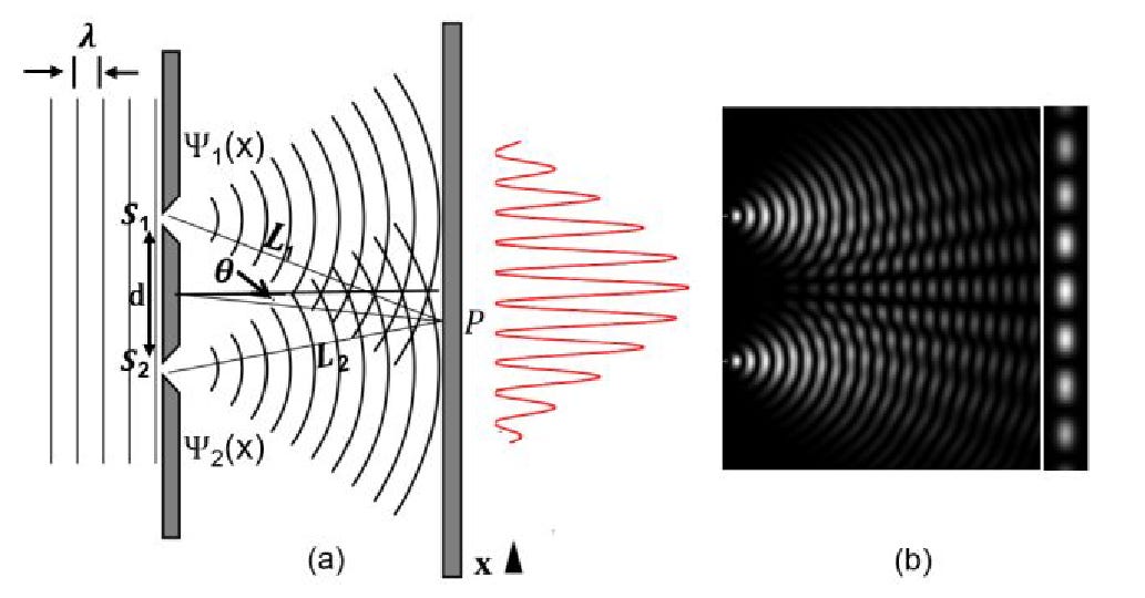
In general, such a wavefront could belong to water, or light, or sound, etc. As we have seen in the previous section, interference phenomena are a common characteristic of any kind of wave. To test whether light behaves like a wave, ideally, one should use a highly monochromatic source of light, like that of a laser, in order to obtain a single wavelength front.1
More specifically, the small slits must be about the size of the wavelength of the incoming wave. If the wave were to have a much larger wavelength than the size of the slits, it would simply bounce back or be absorbed by the wall as if there were no pinholes or slits at all. If, on the other hand, the wavelength of the incoming wave were much smaller than the slits, then it would experience almost no diffraction. While, if the wavelength is comparable with the slit size, then we will observe a situation like that shown in Fig.1b. After the slits’ apertures, and because of the diffraction of the transverse plane wavefront, two concentric outgoing wavefronts form (in a three-dimensional volume, these would be a pair of spherical wavefronts).
Diffraction is characteristic of every wave phenomenon and occurs whenever a wave encounters an obstacle of a size comparable to its wavelength. Every time light passes by an edge or a little aperture that is comparable in size to its wavelength, it gets diffracted—that is, deflected, bent and deformed. You may have experienced this in your daily life. If you look at a source of light from the edges of an object, such as from a cusp angle or through a tiny pinhole, you will see how the contour, the lineaments of the figure of the object, get a bit distorted and smeared, eventually noticing unsharp shadows—what will turn out to be the minima of the interference fringes.
Notice how the two outcoming waves have an intensity which has an angular dependence—that is, more intense head-on than seen from the sides. These two spherical fronts travel forward in the direction of the screen where they will interfere with each other.
The phase difference between the two waves—that one coming from one slit and the other from the other slit—is determined by the length difference of the two lines traced from the two slits S1 and S2 and meeting at some point P on the screen—that is, the two paths L1 and L2. In fact, it is the difference between these two paths that the two waves experience in reaching the screen at that point which is responsible for the interference phenomenon. This will form the characteristic interference fringes along the detection screen (in Fig.1 along the vertical x-direction). It is this phase difference which varies along the detection screen, which determines whether we will have constructive or destructive interference or something in between. The bright bands are, the regions where we have constructive interference, whereas the darker lines represent the destructive one. Overall, the interference pattern depends on the wavelength of the light, the slits’ aperture size, their separation and the distance between the slits and the screen.
Notice also that the interference occurs everywhere, not only on the screen. The screen serves the sole purpose of allowing for its detection and making it visible, but waves overlap, sum or subtract each other everywhere in space, as Fig. 1b shows.
Let us put this into a bit more rigorous mathematical setting. In the case of the double-slit, the two light beams emerging from the respective slits can be described by the two waves ψ1(x) and ψ2(x). The of the light signal on the detection screen is given by θ, the angle between a horizontal line centered between the two slits and that connecting at some point P on the detection screen.
However, the two waves will reach the detection screen in P along two paths having different lengths. This is because the distance L1 traveled by wave ψ1 from S1 to P will, in general, be different from the distance L2 traveled by wave ψ2 from S2 to the same point P. Therefore, even though the two waves have exactly the same wavelength λ and amplitude ψ0, they will nevertheless reach an observer in P along two different paths with phase ϕ1 and ϕ2. The relative phase difference δϕ = |ϕ2 − ϕ1|, will be determined by the absolute length difference of the two paths δL = |L2 − L1|, which ultimately depends on the position of point P on the screen along the vertical x-axis or, equivalently, by the detection angle θ. The angular dependence of the phase relation between the two wavefronts is a major point that must be considered accurately and that we will encounter repeatedly. Once a point P on the screen is chosen, this relative phase is constant—it does not depend on time— and the wavefronts are said to be coherent.
It is precisely this angular dependence of the phase relationship between the two wavefronts that enables us to distinguish waves from particles. In the case of waves, differences in path length from the two slits to a given point on the screen translate into phase differences, which in turn produce constructive and destructive interference. If light were composed merely of classical particles, the difference in the paths traveled from the slits to the screen would be irrelevant, since there would be no coherent wavefronts whose relative phase could generate an interference pattern.
Now, if one calculates the complex squared modulus of the sum of the two beams ψ1(x) and ψ2(x) in x = P , that is the overall intensity appearing on the screen, and taking into account the phase difference between the two interfering waves in P in dependence on the detection angle θ, one gets the following result:2
The resultant interference signal on the screen has three terms: the two waves squared modulus plus twice the real part of the product of one conjugate wave function times the other one. Because the squared modulus of wave functions represents their intensities, I1(x) and I2(x), we can set them equal as |ψ1(x)|^2 = I1(x) and |ψ2(x)|^2 = I2(x). However, there is also the third term which emerges from this calculation and which makes clear that, in general, the intensity at a point in space resulting from two interfering waves is not the sum of their intensities. The third extra term is called the interference term. According to the above defined value δϕ of the relative phase shift between the two beams, one has constructive interference (the interference term is positive when δϕ in the cosine function is an even multiple of 2π and adds up) or destructive interference (the interference term is negative when δϕ in the cosine function is an odd multiple of π and subtracts). This interference term modulates the intensity of the signal according to the observation angle. Or, in other words, if we move a detector that measures the intensity along the x-direction at each point, the intensity will oscillate up and down according to the peaks and valleys determined by the cos(δϕ) function, which adds or subtracts an amount proportional to the interference term from the term I1(x) + I2(x) in Eq.1.
When a photograph is taken (say, with a ccd-camera), each pixel will display a fixed signal intensity (twice the intensity of the single slit light beam) plus or minus an intensity which changes along the vertical axis. Maximum intensity and minimum intensity appear due to constructive or destructive interference, respectively. The white interference fringes on a black background or, displaying it in a more technical manner, its mathematical reconstruction is usually depicted with a curve like the red function graph in Fig. 1a. The intensity of the fringes decreases with the angle because of the angular dependence of the amplitude of the two outcoming beams (as shown in Fig. 1b), that is, they are damped out by a diffraction envelope.3
This interference term is a quite frequent manifestation in QM where particles overlap or interact with each other and makes it appearance wherever one deals with waves having constant relative phases. It is an example of a system in ‘coherent state’ . Would the relative phase between the two beams not be constant (that is, δϕ vary randomly in time, such as in the case of the overlap of EM waves of two different light sources) this interference term would be zero (the randomicity would “flatten it out,” so to speak) and only the diffraction effects would be present and one speaks of an incoherent state . Later we shall see how the state of a quantum systems can loose its coherence (for example due to environmental interaction), then one speaks of “quantum decoherence.”
So, what did Young observe? Of course, you know the answer. The candlelight projected through the two slits produced exactly the interference fringes predicted by the wave theory and the above calculations. Light fully displays a wave behavior. Huygens’ wave-like hypothesis appeared to be confirmed, whereas Newton’s particle theory seemed to be refuted.
Thus, the double-slit helped us to discern between a wave and a particle. A wave will always show up with an interference phenomenon, and the double-slit experiment is the most classical device which makes this clear. Newton firmly believed that light is made up of particles. But later, in 1801, Young’s double-slit experiment (like many other experimental facts showing interference phenomena) suggested unequivocally that light behaves like a wave.
So, what did Young observe, in 1801? Of course, you know the answer. The candlelight projected through the two slits produced exactly the interference fringes predicted by the wave theory and the above calculations. Light fully displays a wave behavior. Huygens’ wave-like hypothesis appeared to be confirmed, whereas Newton’s particle theory seemed to be refuted. Young’s double-slit experiment suggested unequivocally that light behaves like a wave.
Thus, the double-slit helped us to discern between a wave and a particle. A wave will always show up with an interference phenomenon, and the double-slit experiment is the most classical device which makes this clear. If light is made of particles, interference could not become visible. We can speak of interference of waves, but there is no meaning in saying that two particles interfere with each other. From the standpoint of CP, and that of our everyday experience, it would make even less sense to speak of a single particle traversing both slits at the same time and interfering with itself like a wave once it hits a screen.
Or does it have a meaning? We shall see how subtle Nature can be. Quantum theory will teach us a very interesting and deep lesson.
Of course, this was not feasible in Young’s time; he relied on a candle as a light source. With the use of optical filters, however, interference fringes can still be obtained, even though they typically appear in several colors rather than as a purely monochromatic pattern.
The proof is a bit boring algebra that would go beyond the scope of this introductory approach; the interested reader can find proof in my Vol. I book’s appendix, and a more general proof extended also to polarized beams in Vol. II
For sake of simplicity this latter aspect has not been taken into account in Eq. 1, but the interested reader can graph fringes, as also shown in the figures, just by multiplying it with an exponential damping factor, such as e^(-(δϕ/10)^2).
There is a growing, dogmatic trend to reduce everything to wave mechanics, often ignoring physical reality and experimental data. While we know light possesses intrinsic electromagnetic wave properties like frequency, projecting these exact properties onto matter—like an electron—often feels like a mathematical imposition rather than a reflection of its physical nature.
Consider the double-slit experiment. When you fire heavy molecules through the slits, modeling them purely as chaotic wave functions overcomplicates the reality. If you match the momentum of those heavy molecules to the momentum of photons (and yes, photons are real, localized entities), you get the exact same interference pattern.
This experimental data suggests that the interference pattern is not the result of mystical 'matter waves,' but rather a product of the actual momentum interacting with the physical medium of the slits. It doesn't matter what projectile you throw at the slits; what dictates the resulting pattern is the physical interaction of its momentum.