
Waves strike back again - Book Excerpt #8
Bragg diffraction

This is section II.5 (that builds upon the previous section here) of the first volume of my book, “Quantum Physics: An Overview of a Weird World.” I plan to post regular updates, including minor and substantial revisions, on Substack. For the full table of contents and guidance on how to follow the book as it unfolds, please click here.
We are now in a position to analyze wave interference in real-world physical phenomena. We can begin with a classical example—what one observes in thin film interference. This will open up the way for us to understand Bragg diffraction and the wave-particle duality.
In Fig. 1 you can see a couple of light rays with a certain angle of incidence reflected by a thin film surface. This thin film surface could be for example made of water, or the mixing of oil and water on the road after a rainstorm, or, as in this case here, that of a soap bubble. The nice coloring of oil films or, as we enjoyed as children, of soap bubbles, is an interference phenomenon that can be explained as follows.
These films have a very small but non-negligible thickness limited by an upper and lower layer. The reflection of light onto these layers can be visualized as a first beam, beam A, that goes unperturbed through the upper layer and will be reflected by the lower layer of the film, and a second beam B which is reflected by the upper layer. If we examine the situation carefully, it is easy to recognize that there is a difference in the travelled path between the two light rays. Even if both light rays are emitted at the same time from the same source and arrive with the same angle—that is, they are parallel to each other—when they reach the two thin film layers, they are nevertheless reflected at different depths and therefore acquire a path difference l, which implies a phase difference relative to each other (the little segment of length l, in Fig. 1).
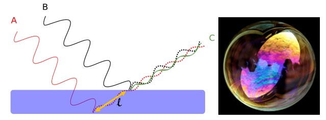
The two beams then sum up and superimpose after the reflection, interfering according to their phase difference. This phase difference is determined only by the incident angle once we fix the thickness of the film and its refractive index (a dimensionless number which tells how much light is refracted and reflected or, equivalently, how fast it travels in a medium). This implies also that the outgoing light can interfere constructively, destructively, or somewhere in between, for every specific reflection angle. We will observe the resultant waves varying in intensity and wavelength along the different angular positions where we place our eyes. This is why we can observe the beautiful plurality of color patterns on the surface of a soap bubble.
The same thin film interference works not only with water layers in visible light but also for atomic crystal lattice layers at X-ray wavelengths. In the latter case we need very short EM wavelengths because the distances that separate the different atomic crystalline layers (also called crystallographic planes) are very small, of the order of few atomic sizes. Obviously, at these wavelengths, we will no longer deal with color patterns since X-rays are well beyond the human-visible light spectrum, but the underlying principle remains the same.
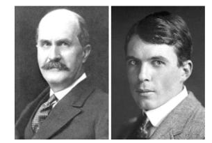
In 1913, W. H. Bragg and his son W. L. Bragg, two British physicists, discovered how crystalline solids produce patterns of reflected X-rays that can be interpreted only as interference patterns, nowadays called Bragg diffraction patterns. They observed intense maxima and minima of reflected radiation, depending on the wavelength and angle of incidence—that is, they could not be observed for reflected radiation of longer wavelengths.
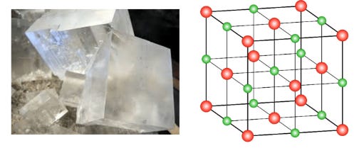
In fact, more precisely, at the atomic scale, we can no longer speak of classical reflections on a surface layer; we must conceive of the photons (or waves) as absorbed by the atom and re-emitted in all directions in the form of spherical waves. All these spherical wavefronts then sum up and form an interference pattern somewhere, for example on a screen. Let us take a typical example of an atomic lattice: a salt crystal, which is nothing other than sodium chloride, a crystal made by sodium and chlorine atoms (depicted in Fig. 3 with larger and smaller atoms, respectively).
The function of the thin film we considered in the example of the soap
bubble with liquid layers can now be taken up by the atomic layers of the
salt crystal lattice. Here again, two incident and parallel light beams will be
reflected by two underlying crystallographic planes.
There are essentially three physical variables that determine how the beams will be diffracted and will interfere—that is, how the outgoing waves will display their relative phase shift which gives rise to the interference pattern. First, all depends from the wavelength λ of the EM wave. Second, what determines the phase shift induced by the path difference is also the distance d which separates the atomic layers. This causes a path difference (the short wavy segment that connects the two atomic layers in Fig. 1), and consequently a phase difference between the two emerging beams. Finally, we must also choose the angle of incidence, or equivalently the scattering angle θ.
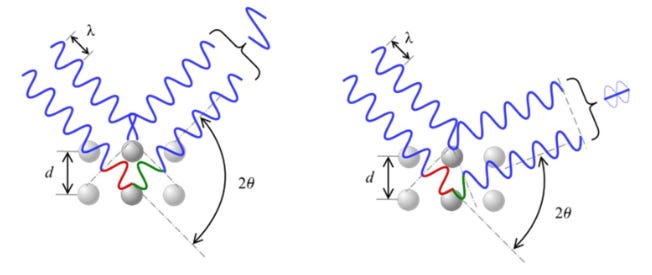
The appropriate combination of these three parameters will give rise to constructive or destructive interference. Once we have chosen some material with some specific chemical composition, the crystal lattice layers distance d is fixed. If we maintain the wavelength λ of our X-ray source as constant, the wavelength is fixed too.
This means that, if we observe the outgoing interfering waves at different angles, then we will see constructive interference (Fig. 4 left) or destructive interference (Fig. 4 right), due to the fact that they correspond to different paths of the light beams, giving rise to the respective type of interference.
This can be summarized by Bragg’s law, which tells us the conditions for constructive interference from successive crystallographic planes:
For each integer (n=1, 2, 3,...) we are able to calculate each angle where the maxima will occur.
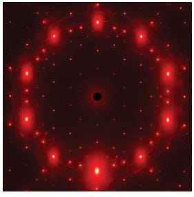
So, if we look at different scattering angles at the same time, for example on the screen of a photographic plate or a CCD sensor placed in such a manner that several beams with several angles are captured throughout the sensor’s surface, then we will observe a very interesting diffraction pattern, as those in Fig. 5.
Here we have a beautiful symmetric pattern obtained by X-ray interference through a crystal. From these patterns, physicists and chemists are able to infer the crystalline atomic structure of substances. Therefore, Bragg diffraction allows us to reconstruct the geometrical displacement of atoms in the lattices, in some sense; we might say that it is like a microscope that indirectly furnishes images of the chemical structure of substances.
Admittedly, this is a simplified model. In practice, other planes also contribute to the overall effect, though to a lesser degree, and these will cause many more small peaks and complex patterns. But for our purposes here, this model suffices to illustrate the principle of Bragg’s diffraction.
But what does this have to do with QM? Well, a lot, as we will see in the next essay.